9. Configuring NOAA Cloud Service Providers
The NOAA Cloud Service Providers (CSPs) support the forecast-only, coupled, and GEFS configurations for global-workflow. Once a suitable CSP instance and cluster is defined/created, the global-workflow may be executed similarly to the on-premises (on-prem) machines. Currently, the global-workflow supports the following instance and storage types as a function of CSP and forecast resolution.
Cloud Service Provider |
Global Workflow Resolution |
Global Workflow Application |
Instance Type |
Partition |
File System |
|---|---|---|---|---|---|
Amazon Web Services ParallelWorks |
C48, C96, C192, C384 |
|
|
|
|
Azure ParallelWorks |
C48, C96, C192, C384 |
|
|
|
|
GCP ParallelWorks |
C48, C96, C192, C384 |
|
|
|
|
Instructions regarding configuring the respective CSP instances and clusters follow.
9.1. Login to the NOAA CSP
Log in to the NOAA cloud, and into the resources configuration. The user should arrive at the following screen as in Figure 9.1. Click the blue box indicated by the red arrow to login.
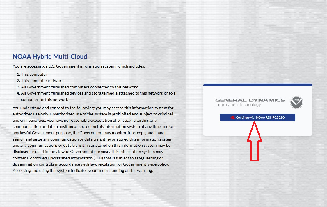
Fig. 9.1 NOAA-PARALLELWORKS Home Page
As shown in Figure 9.2, Fill the Username / Email box with your username or NOAA email (usually in “FirstName.LastName” format).
Note that the Username or email query field is case-sensitive.
Then enter the respective Pin + RSA combination using the same RSA token application used
for access to other RDHPCS machines (e.g., Ursa/Hera, Gaea).
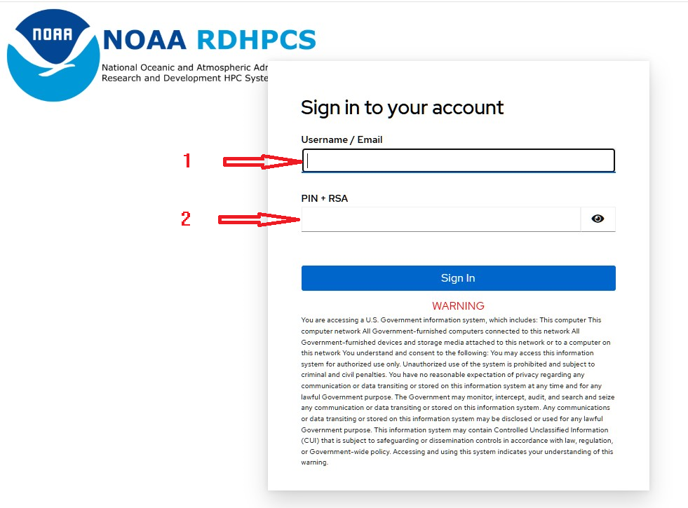
Fig. 9.2 NOAA-SSO-PARALLELWORKS Login Page
9.2. Configure the NOAA CSP Instance
Once logged into the NOAA CSP, navigate to the Marketplace section
in the left sidebar as indicated by the red arrow in Figure 9.3, and click.
Scroll down to select “AWS EPIC Wei c7i.24xlarge”, circled in red.
Note that the current global-workflow is now using Rocky8 spack-stack.
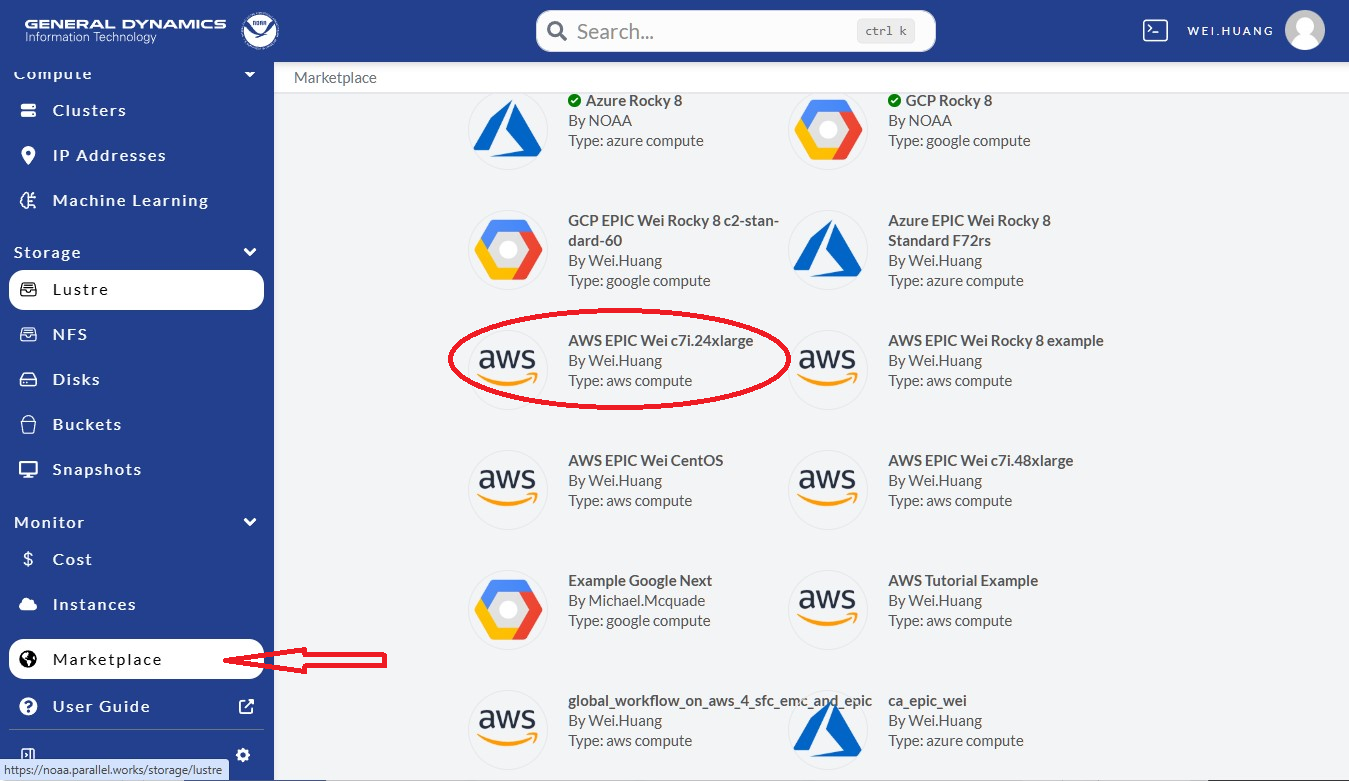
Fig. 9.3 ParallelWorks Marketplace
Next, click “Fork latest” as shown in the red-circle in Figure 9.4.
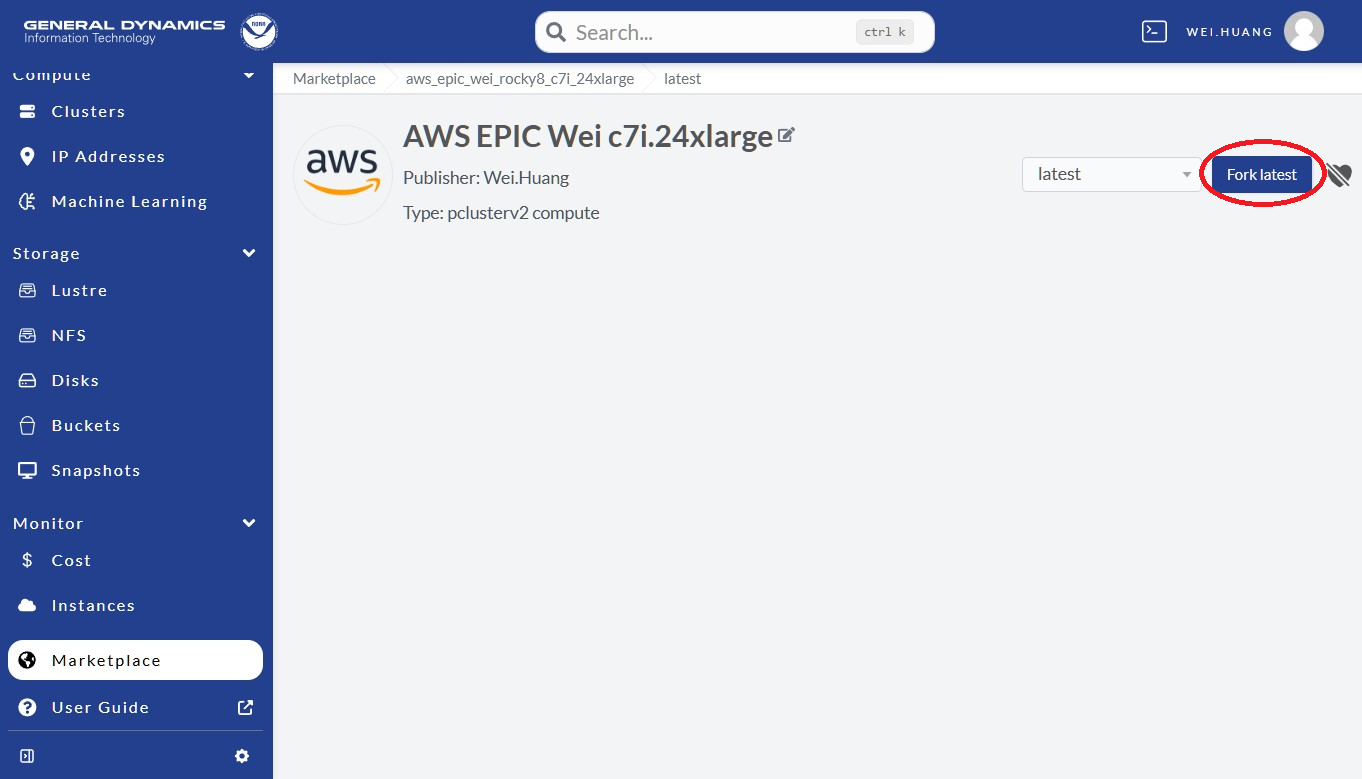
Fig. 9.4 Fork Instance From Marketplace
Please provide a unique name in the “New compute node” field for the instance
(see the box pointer by the red arrow in Figure 9.5).
Best practices suggest one that is clear, concise, and relevant to the application.
Click Fork (in the red-circle) to fork an instance.
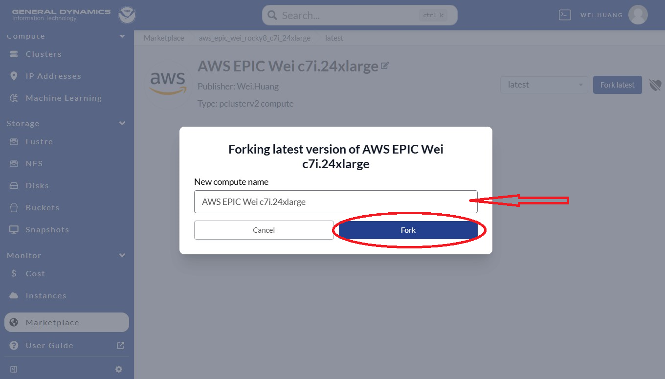
Fig. 9.5 Create the Fork
Now, an instance is forked, and it is time to configure the cluster. Follow these steps as shown in Figure 9.6:
Select a Resource Account; usually it is NOAA AWS Commercial Vault.
Select a Group, which will be something like:
ca-epic,ca-sfs-emc, etc.Copy and paste your public key (e.g.,
.ssh/id_rsa.pub,.ssh/id_dsa.pubfrom your laptop).Modify User Bootstrap. If you are not using the
ca-epicgroup, please UNCOMMENT line 2.Keep Health Check as it is.
Click Save Changes at the top-right as shown in the red circle.
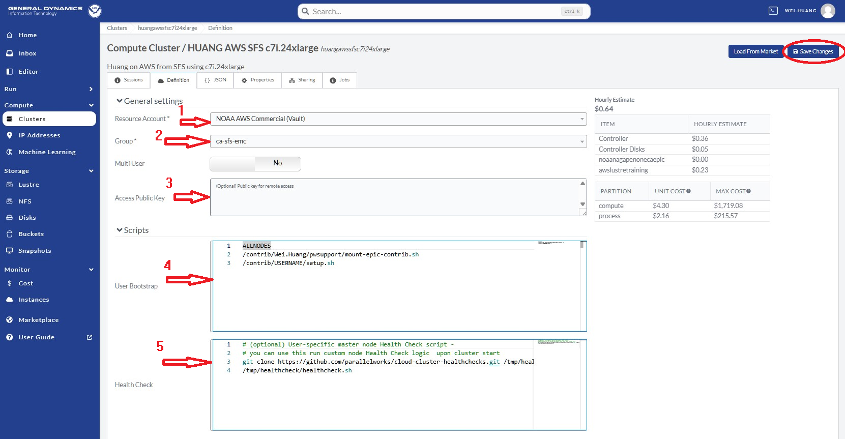
Fig. 9.6 Configure & Save the Instance
NOAA ParallelWorks (PW) currently provides 3 CSPs: AWS (Amazon Web Services), Azure (Microsoft Azure), and GCP (Google Cloud Platform). Existing clusters may also be modified. However, it is best practice to fork from Marketplace with something similar to your requests (rather than modifying an existing cluster).
9.3. Add CSP Lustre Filesystem
To run global-workflow on CSPs, we need to attach the /lustre filesystem as a run directory.
First, we need to add/define our /lustre filesystem.
To do so, navigate to the middle of the NOAA PW website left side panel and select Lustre
(see the red arrow in Figure 9.7), and then click Add Storage
at the top right, as shown in the red circle.
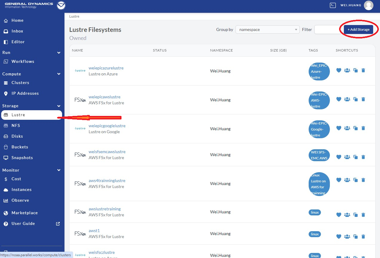
Fig. 9.7 Add Lustre Storage
Select FSx for the AWS FSx /lustre filesystem as shown in the red circle.
Define /lustre with steps in Figure 9.8:
Provide a clear and meaningful Resource name, as shown by the first red arrow
Provide a short sentence for Description, as shown in the second red arrow
Choose linux for Tag, as shown by red arrow #3
Click Add Storage as in the red box at the top right corner.
This will create a /lustre filesystem template after clicking on the red square shown in Figure 9.8.
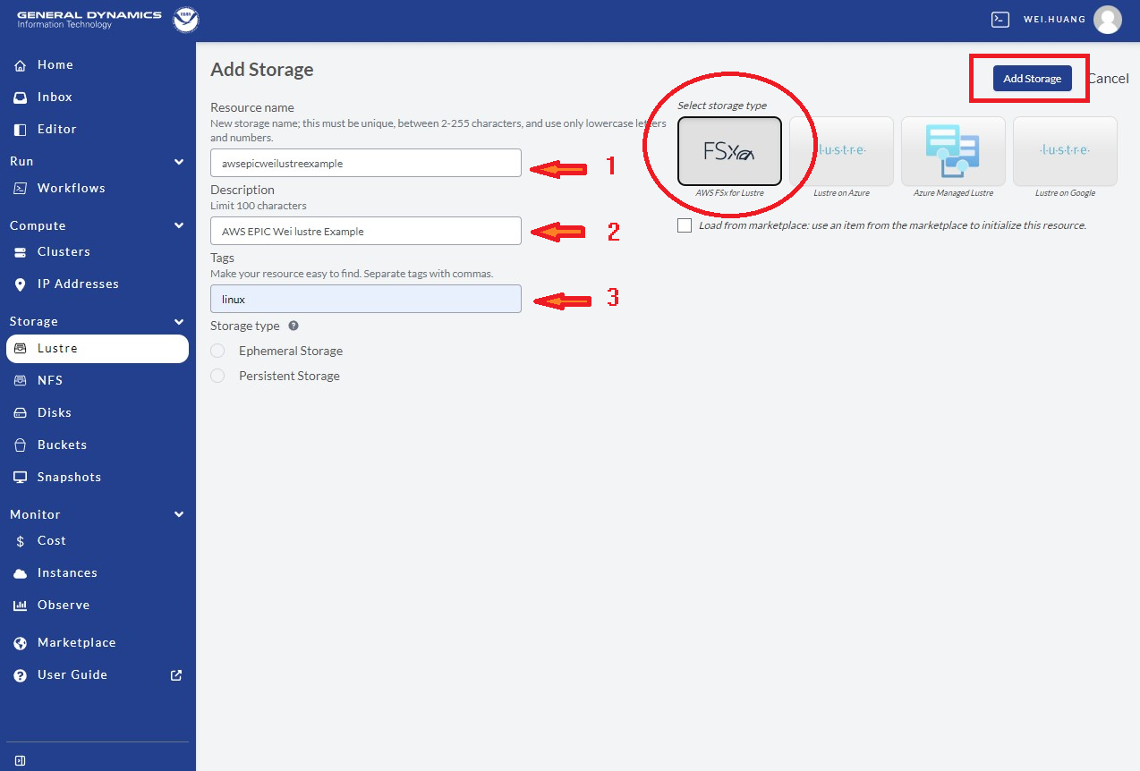
Fig. 9.8 Define Lustre Attributes
After creating the template, we need to fill in information for this /lustre filesystem.
To do so, go to the NOAA PW website, and click Lustre on the left side panel, as
indicated by red arrow 1 in Figure 9.9. Then select the filesystem defined by Resource name in Figure 9.8 above,
as shown in the red box. Here, the user can delete this resource if not needed by
clicking the trash can (indicated by red arrow 2 in Figure 9.9).
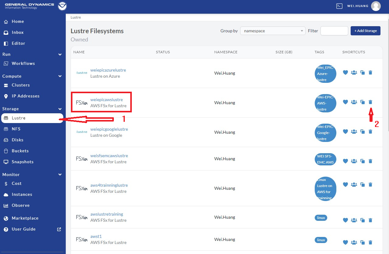
Fig. 9.9 Show Lustre on the PW page
By clicking the filesystem in the red box of the image above,
users will be led to the /lustre definition page.
Then follow the steps illustrated in Figure 9.10 below:
Choose a size in the Storage Capacity (GB) box, as indicated by red arrow 1. There is a minimum of 1200 for AWS. For the C48 ATM/GEFS case this will be enough. For SFS-C96 case or C768 ATM/S2S case, it should probably be increased to 12000.
For File System Deployment, choose “SCRATCH_2” for now as indicated by red arrow 2. Do not use SCRATCH_1, as it is used for testing by PW.
Choose NONE for File System Compression as pointed by red arrow 3. Only choose LZ4 if you understand what it means.
Leave S3 Import Path and S3 Export Path blank for now.
Click Save Changes in the red circle to save the definition/changes made.
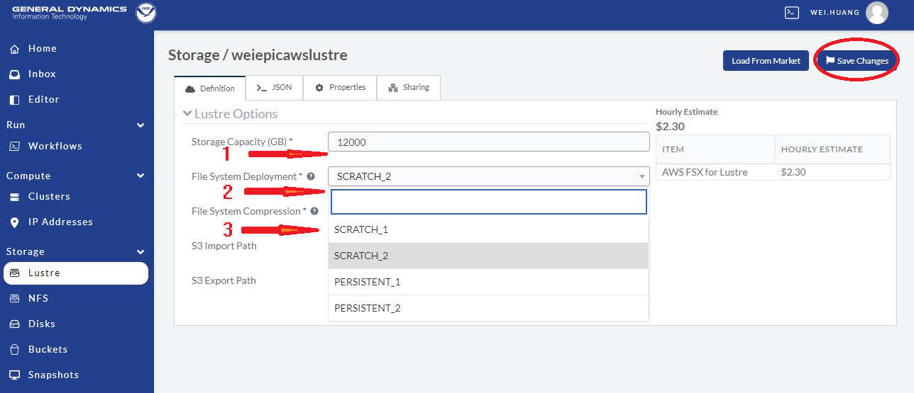
Fig. 9.10 Defining the Lustre Filesystem Capacity
For the storage to be allocated for the global-workflow application,
it is suggested that the Mount Point be /lustre. Once the storage
has been configured, follow the steps below to attach the /lustre filesystem.
9.4. Attach CSP Lustre Filesystem
Now we need to attach the defined filesystem to our cluster.
Go back to our the NOAA PW website (https://noaa.parallel.works), and click Cluster
as shown in Figure 9.11 below, then select the cluster you made (e.g., AWS EPIC WEI c7i.24xlarge cluster, as shown in the red box below).
Note, one can remove/delete this cluster if no longer needed by
clicking the trash can shown in the red circle at right.
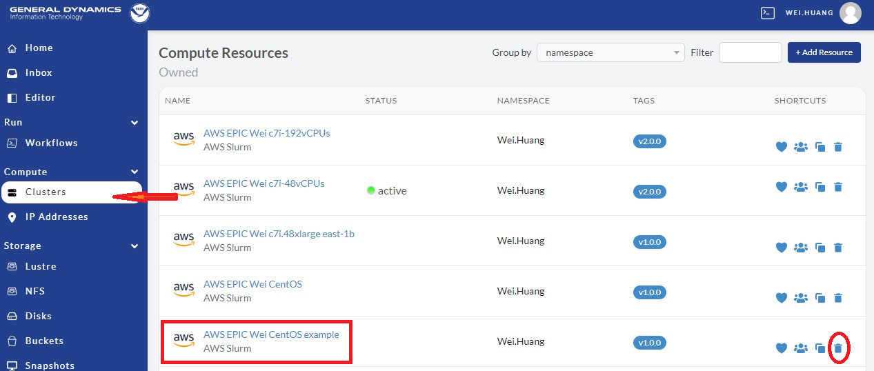
Fig. 9.11 Add Attached Filesystems
When we get into the cluster page, click the Definition in the top menu as in the red-box in Figure 9.12. Then we can attach the defined filesystems. When finished, remeber to click Save Changes to save the changes.
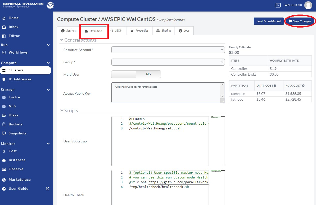
Fig. 9.12 Add Attached /lustre and/or /bucket Filesystems
Scroll down to the bottom as show in Figure 9.13, and click Add Attached Filesystems as in the red circle.
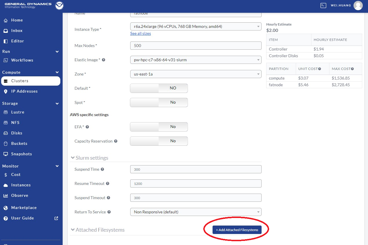
Fig. 9.13 Attach /lustre and/or /bucket Filesystems
After clicking Add Attached Filesystems, go to Attached Filesystems settings, and follow the steps listed here, which are also shown in Figure 9.14.
In the Storage box, select the lustre filesystem defined above, as in red arrow 1.
In the Mount Point box, name it
/lustre(the common and default choice), as indicated by red arrow 2. If you choose a different name, make sure that the name chosen here uses the name from the global-workflow setup step.
If you have a S3 bucket, one can attached as:
In the Storage box, select the bucket you want to use, as in red arrow 3.
In the Mount Point box, name it
/bucket(the common and default choice) as indicated by red arrow 4.
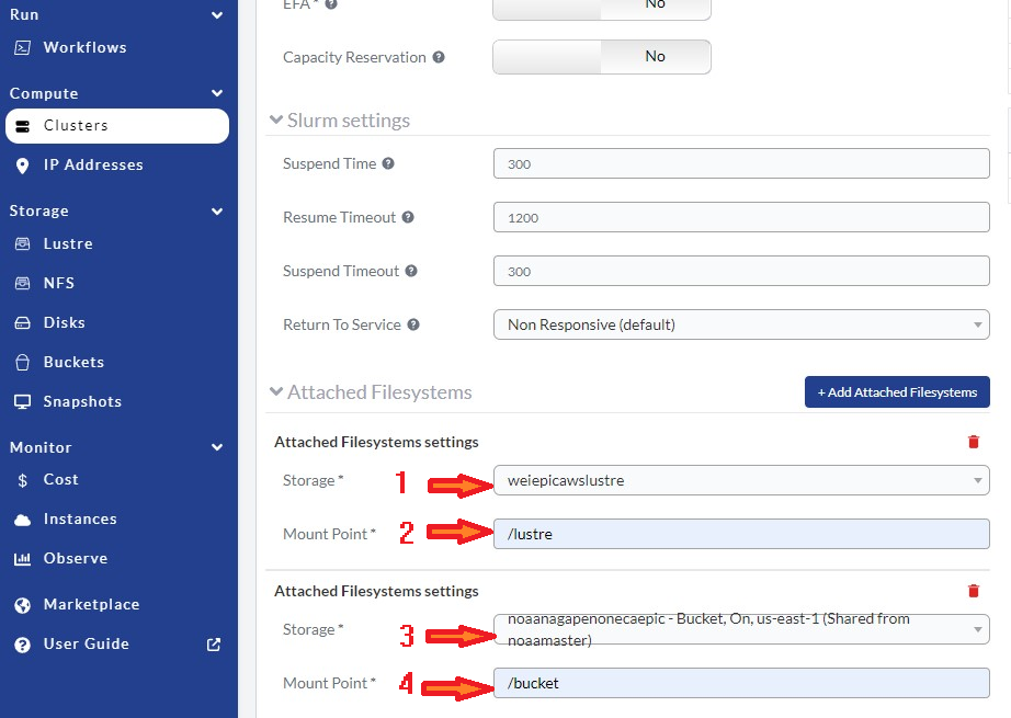
Fig. 9.14 Adjust Attached /lustre and/or /bucket Filesystem Settings
Always remember to click Save Changes after making any changes to the cluster.
9.5. Using the NOAA CSP Cluster
To activate the cluster, click Clusters on the left panel of the NOAA PW website shown in Figure 9.15, as indicated by the red arrow. Then click the Sessions button in the red square, and click the power button in the red circle. The cluster status is denoted by the color-coded button on the right: red means stopped; orange means requested; green means active. The amount of time required to start the cluster varies and is not immediate; it may take several minutes (often 10-20) for the cluster to become active.
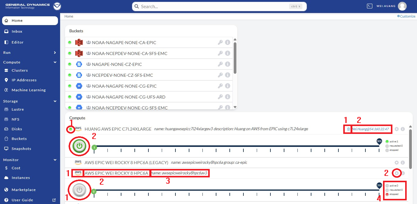
Fig. 9.15 Activate the Cluster
When the cluster is activated, users will see the following indicators of success listed below as seen in Figure 9.16:
A green dot on the left beside the AWS logo means that the cluster is active (indicated by red arrow 1).
A green dot on the right labeled “active” means that the cluster is active (indicated by red arrow 2).
A green power button means the cluster is active (indicated by red arrow 3).
Clicking the clipboard icon (blue square with arrow inside), indicated by red arrow 4 will copy the cluster’s IP address into the clipboard. Then, you can open a laptop terminal window (such as xterm), and run
ssh username@the-ip-address. This will connect you to the AWS cluster, and you can do your work there.Alternatively, users can click directly on the
username@the-ip-address, and a PW web terminal will appear at the bottom of the website. Users can work through this terminal to use their AWS cluster.
Please note, as soon as the cluster is activated, AWS/PW starts charging you for use of the cluster. As this cluster is exclusive for yourself, AWS keeps charging you as long as the cluster is active. For running global-workflow, one needs to keep the cluster active if there are any Rocoto jobs running because Rocoto uses crontab, which needs the cluster active all the time, or the crontab job will be terminated.
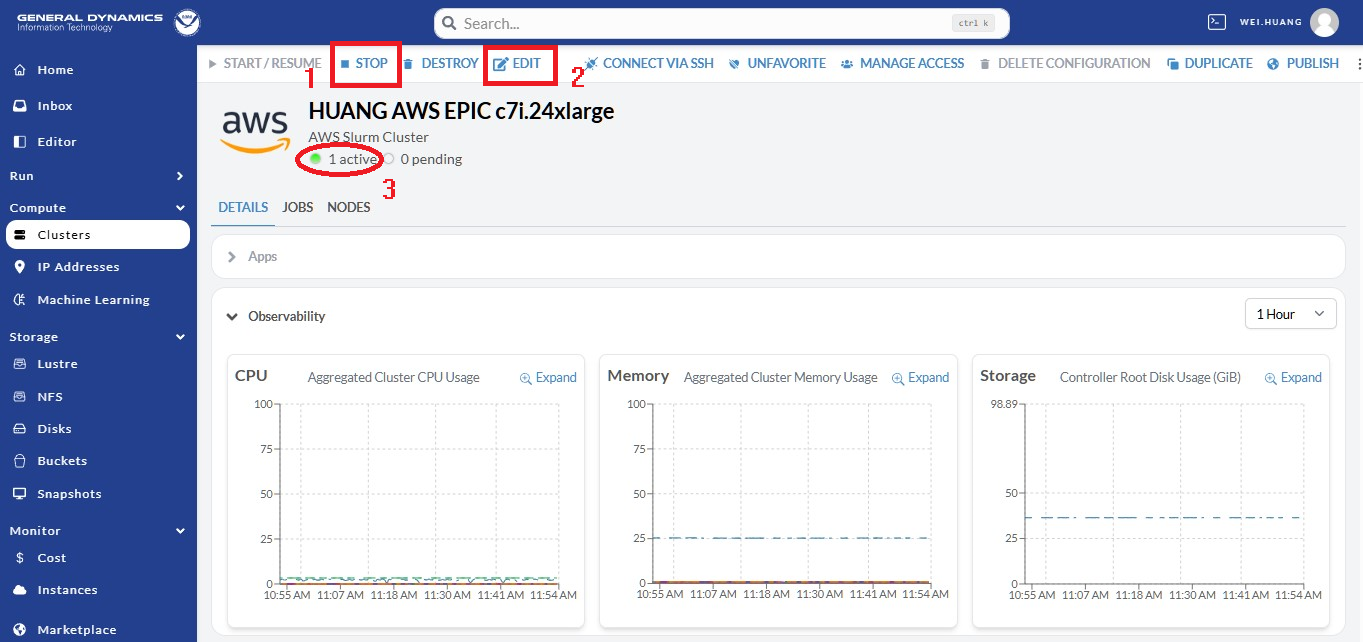
Fig. 9.16 Knowing the Cluster
After finishing your work on the AWS cluster, you should terminate/stop the cluster, unless you have reasons to keep it active. To stop/terminate the cluster, go to the cluster session, and click the green power button as show in Figure 9.17. A window will pop up; click the red Turn Off button to switch off the cluster.
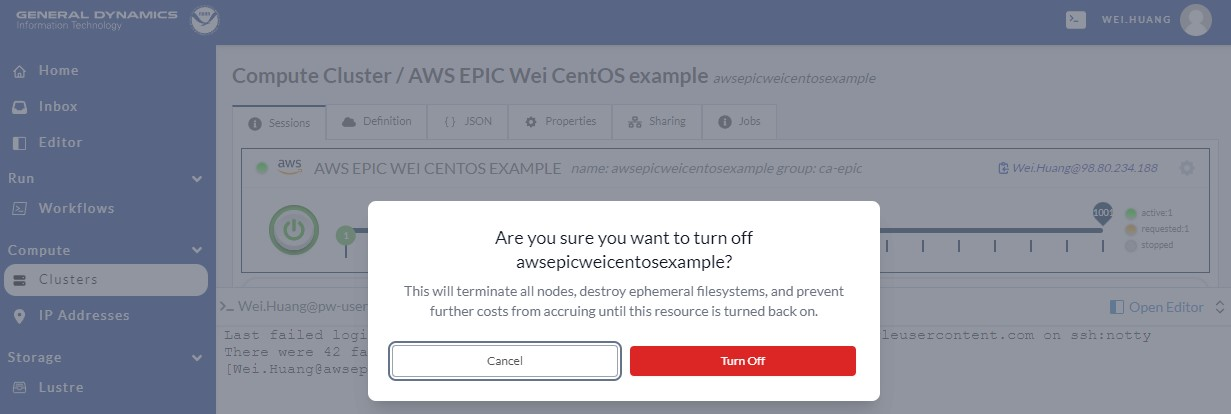
Fig. 9.17 Terminating the Cluster
9.6. Running the Global Workflow
Assuming you have an AWS cluster running, after logging in to the cluster through ssh from your laptop terminal
or accessing the cluster from your web terminal, you can start to clone, compile, and run global-workflow.
Clone global-workflow (assumes you have set up access to GitHub):
cd /contrib/$USER   #you should have a username and have a directory at /contrib, where we save our permanent files.
git clone --recursive git@github.com:NOAA-EMC/global-workflow.git global-workflow
Compile global-workflow:
cd /contrib/$USER/global-workflow
cd sorc
build_all.sh      # or similar command to compile for gefs, or others.
link_workflow.sh  # after build_all.sh finished successfully
As users may define a very small cluster as controller, one may use the script below to compile in compute node. Save the this script in a file, say,
com.slurm, and submit this job with commandsbatch com.slurm:#!/bin/bash #SBATCH --job-name=compile #SBATCH --account=$USER #SBATCH --qos=batch #SBATCH --partition=compute #SBATCH -t 01:15:00 #SBATCH --nodes=1 #SBATCH -o compile.%J.log #SBATCH --exclusive gwhome=/contrib/Wei.Huang/src/global-workflow # Change this to your own "global-workflow" source directory cd ${gwhome}/sorc source ${gwhome}/dev/ush/gw_setup.sh #build_all.sh build_all.sh -w link_workflow.sh
Run global-workflow C48 ATM test case (assumes user has
/lustrefilesystem attached):cd /contrib/$USER/global-workflow HPC_ACCOUNT=${USER} pslot=c48atm RUNTESTS=/lustre/$USER/run \ ./workflow/create_experiment.py \ --yaml ci/cases/pr/C48_ATM.yaml cd /lustre/$USER/run/EXPDIR/c48atm crontab c48atm.crontab
EPIC has copied the C48 and C96 ATM, GEFS, and some other data to AWS, and the current code has been set up to use those data. If users want to run their own case, they need to make changes to the IC path and others to make it work. The execution of the global-workflow should now follow the same steps as those for the RDHPCS on-premises hosts.